
WDM Technologies for 5G Carrying Network
Oct 28, 2020
5G Application Scenarios
The development of 5G networks starting in 2019 is generally believed to bring changes not limited to people’s daily life. It will support the evolution of Internet from mobile internet to intelligent internet, which will influence the industrial-ecology deeply.
The international standard organization 3GPP defined the three main application scenarios of 5G: eMBB (Enhance Mobile Broadband), uRLLC (Ultra-Reliable Low Latency Communications), mMTC (Massive Machine Type Communication). eMBB requires the bandwidth experienced by the customers to be more than 1Gbps supporting mobile broadband surfaces such as 3D and ultra-high definition video. uRLLC requires the transmitting delay to be <1ms supporting real time applications such as self-driving cars, industrial automation, and remote surgery. mMTC means application in massive internet of things (IOT) which requires high density terminal connection of more than one million per square kilometer.
Structure of the 5G Carrying Network
Build the carrying network before commercial application of 5G. In order to support the aforementioned three application scenarios, the carrying network based on optical fiber is required to be reconstructed. Fig.1 shows a typical structure for 5G carrying network, which usually consists of metro access network, metro aggregation network, metro core network and inter-province backbone network. Considering investigation and operating cost, the radio access network (RAN) of 4G usually employs D-RAN (distributed wireless access) structure based on function division of RRU+BBU, while the 5G system employs C-RAN (centralized or clouded wireless access) structure based on function division of AAU+DU+CU.
Fig.1 Structure of 5G carrying network
The interconnection between the nodes of 5G carrying network is realized through optical transceiver modules and optical fibers. The interconnection between the wireless base station and DU is defined as front-haul. The interconnection between DU and CU is defined as mid-haul. The interconnection between CU and the metro core network is defined as back-haul. The front-haul distance is usually <10/20km and the bit rate of the data interface is 10/25/100Gbps. The mid-haul distance is usually <40km and the bit rate is 25/50/100Gbps.The back-haul distance is usually 40-80km and the bit rate is usually 100/N×100Gbps. The transmitting span of the trans-provincial backbone network is usually hundreds of kilometers and the bit rate is N×100/200/400Gbps.
Fig.2 The front-haul, mid-haul and back-haul link of the 5G carrying network
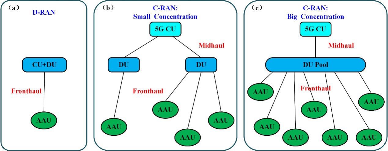
Comparing to the 4G network, the frequency of 5G signal is higher and thus the coverage of a single base station is less. Thus the base stations needed by 5G network is 2-3 times of those by 4G network. C-RAN structure is preferred in the front-haul and mid-haul of 5G network, instead of D-RAN in 4G. There are mainly three advantages for C-RAN. Firstly, the required number of terminal equipment rooms and transmitting equipments is reduced.Thus the cost for station address acquisition, equipment room renting, and data transmission is reduced. Theoretically, the more is the DUs concentrated, the cost down is more. Secondly, the concentrated deployment of DUs facilitates the maintenance. Thus the cost for equipment room construction, equipment maintenance, and power rate is much lower than D-RAN. Thus C-RAN is regarded as the main deployment mode of 5G front-haul network. Thirdly, the DUs are grouped and deployed in a DU pool, or in clouded deployment. Thus the baseband resources can be shared and service cooperation between stations is realized.
Consideration for the Choice of Transmitting Technologies
Optical fiber transmission is widely employed in telecom backbone network and data centers. In order to improve the transmission capacity, WDM technologies are commonly used. However, the concrete transmission technologies are diverse facing different application scenarios.The main factors influencing the choice are power loss and chromatic dispersion of the fiber link. The laser sources (with modulators included) and photon detectors (PDs) are important for the cost of the transmission system and should be considered in choice of proposals. What’s more, the heritage of industrial chain also influence the cost and is one of the factors to be considered.
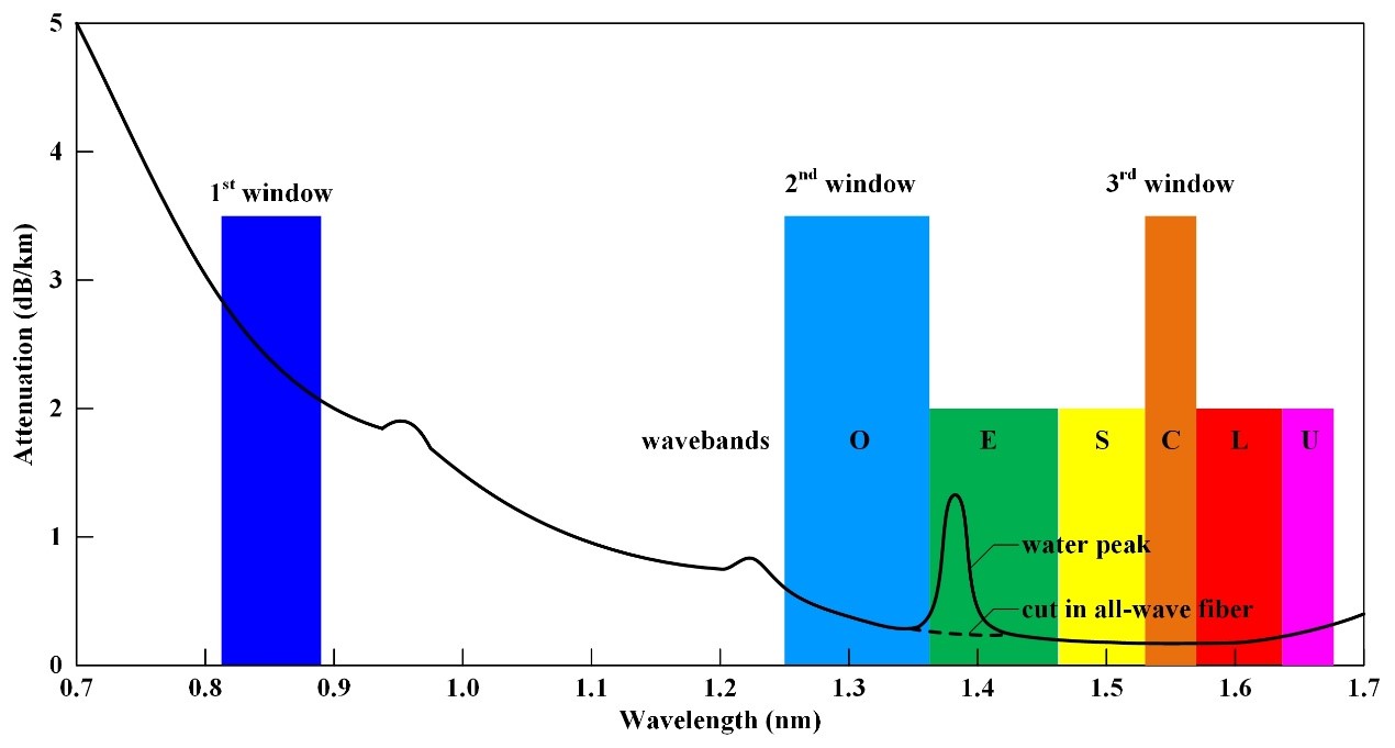
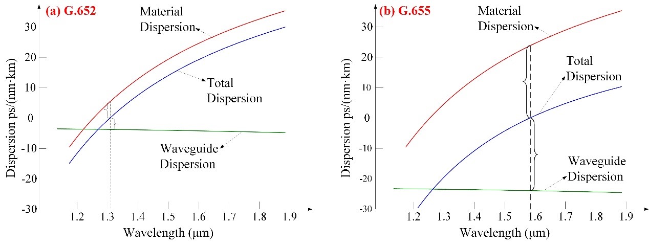
The spectral transmission loss of the common quartz fiber is shown in Fig.3. Its first, second and third transmission windows are centered at 850nm, 1310nm and 1550nm. 850nm is the wavelength selected by the first multimode fiber (MMF) communication system. 1310nm is the zero dispersion wavelength of the conventional single mode fiber (SMF) G.652. As shown in Fig.4(a), the material dispersion and waveguide dispersion counteracts at this wavelength. 1550nm is the wavelength experiencing the lowest loss for quartz fiber. G.655 SMF was developed with its zero dispersion wavelength set with a small shift from 1550nm, as shown in Fig.4(b). Thus low dispersion is obtained at 1550nm-band and non-linear effects, such as four-wave mixing and cross-phase modulation, are avoided.
Fig.3 Spectral transmission loss of quartz fiber
Fig.4 Spectral dispersion of G.652 and G.655 optical fibers
In the engineering applications, the second and third windows in Fig.3 are usually called O-band and C-band, respectively. In order to extend the available transmission band, S-band and L-band are developed neighboring to C-band. What’s more, the water peak around 1385nm (due to OH- absorption) is cut down by further purification of quartz fiber. Thus E-band is developed and the transmission band of quartz fiber is extended to 1260~1620nm. The bandwidth is totally 360nm and the optical fiber is called all-wave fiber.
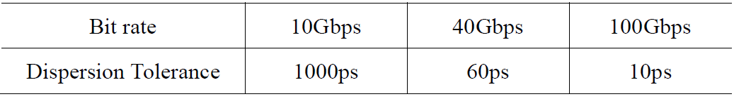
The optical fiber communication system usually employs semi-conductor lasers as the light source. The emission from a semi-conductor laser is not an ideal monochromatic light. It has a certain linewidth. The different wavelength components transmit in different velocity due to dispersion and thus bit error is introduced in high-speed, long-haul transmission system. Optical signals in different bit rate have different dispersion tolerance, as shown in Table 1.
Table 1. Dispersion tolerance for optical signals in different bit rate
The early transmission system in low bit rate usually employ FP lasers with low cost and broader linewidth. However, DFB lasers are necessary for high-speed transmission systems with bit rate ≥10Gbps. When the transmission distance is not too much, people intend to modulate the DFB lasers directly, which are called DML (Direct Modulated Laser) lasers. Direct modulation on the lasers generates chirp effect and broadens the linewidth, which introduces more chromatic dispersion.In order to avoid broadening the linewidth of the lasers to transmit longer distance, external modulation is employed. An EAM (Electro-absorption Modulation) modulator is cascaded behind the laser. The DFB+EAM combination is called EML laser. In order to transmit ever longer distance, LN (Lithium Niobate) modulator is required, which is an electro-optical modulator with Math-Zehnder (MZ) interferometer structure.
Transmission Proposal for Different Application Scenarios
The focus of 5G investment is development of the front-haul and mid-haul networks. The investment is too much and exceeds the affordability of a single telecom operator. China Unicom and China Telecom decide to develop a 5G front-haul network together, while China Mobile cooperates with China Radio and television network Cooperation. A wireless base station should be equipped with upload/download interfaces for three sectors.Under the co-construction and sharing mode, the bandwidth demand for a single base station is doubled and thus six 25G interfaces are required for a 5G base station. For the deployment scenario where 4G and 5G equipments share a base station, 12 front-haul interfaces are required. In some multi-service access region, bandwidth demand is much higher and 24 front-haul interfaces are required for a single base station. Based on above application scenarios, base stations with 12 interfaces will become the main-stream construction in the 5G front-haul network.
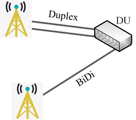
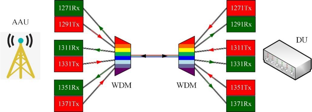
In the 4G front-haul network, BBU is set near to RRU and D-RAN configuration is more adopted. The mostly employed transmission proposal is fiber direct driving. While in the 5G front-haul network, DU is deployed far from AAU. The cost of optical fiber is too much and thus xWDM is popular to save fiber resources. According to the application scenarios and based on the deployed fiber resources, the configurations of 5G front-haul networks can be D-RAN, C-RAN small aggregation and C-RAN massive aggregation, as shown in Fig.5. In the D-RAN deployment, fiber direct driving proposal is selected. BiDi (bi-directional transmission in and single fiber) transmission is suggested to save half of the fiber resources, as shown in Fig.6. In C-RAN small aggregation deployment, six 25G interfaces are required and 6-λ CWDM transmission is proposed, as shown in Fig.7.
Fig.5 The deployment configurations of 5G front-haul network
Fig. 6 Fiber direct driving proposal for front-haul network
Fig.7 6-λ CWDM proposal for 5G front-haul network
In C-RAN massive aggregation deployment, each wireless base station requires 12 high-speed optical interfaces. China Mobile presented a 12-λ MWDM proposal. The 12 wavelengths are listed in Table 2. Based on the 6-λ CWDM laser chips, the emission wavelengths are shifted by 3.5nm to the left and right through TEC tuning. Thus 12 wavelengths are obtained based on the current industrial chain for data transmission. China Telecom selected the 12-λ LWDM proposal. The channel spacing is 800GHz. The 12 wavelengths are listed in Table 3. TEC is required to stabilize the emission wavelength of the laser sources because the wavelength pitch is only 4.3-4.7nm. The power consumption of the optical transceiver module is about 0.5W higher due to the introduction of TEC module.
Table 2. CWDM/MWDMtransmission wavelengths and proposals
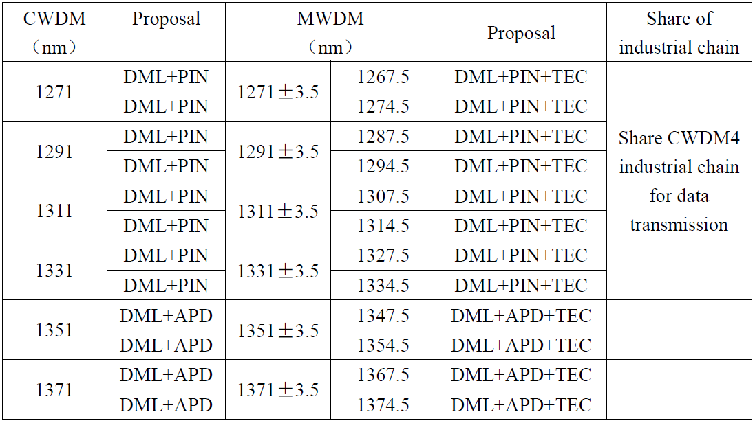
Table 3. LWDM transmission wavelengths and proposals
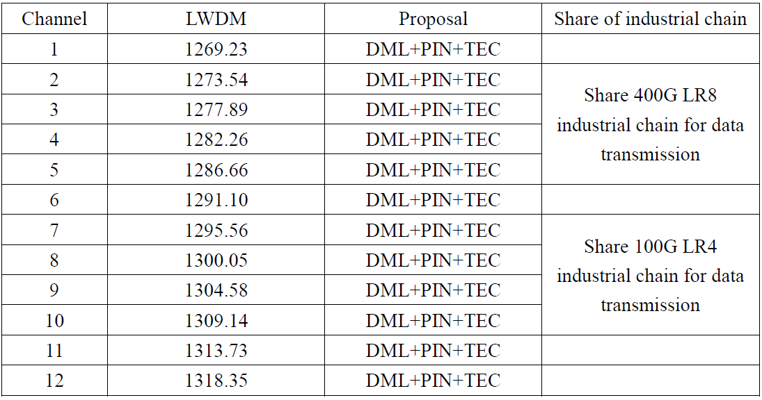
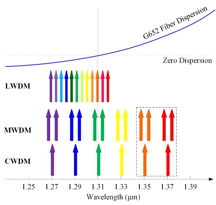
Table 3. LWDM transmission wavelengths and proposals
The different WDM wavelengths and dispersion spectrum of quartz are shown in Fig.8. The latter two wavelengths of 6-λ CWDM is far from the zero-dispersion wavelength 1310nm. In order to compensate for the power loss cost due to dispersion, APD photon detectors are employed which have higher sensitivity. Thus we can see, for the CWDM transmission proposal in Table 2, the laser sources and PDs choose DML+PIN for the former wavelengths, while DML+APD for the latter two wavelengths. For the same reason, the latter four wavelengths of MWDM also employ DML+APD.
Fig. 8 Chromatic dispersion spectrum of optical fiber and WDM proposals for 5G front-haul network
Table 2 and 3 list different WDM transmission proposals for 5G front-haul network, together with the sharing of the current industrial chain in data transmission (for data centers). WDM technologies were first applied in telecom mainly for long-haul transmission in the backbone networks and core networks. DWDM transmission in C-band (1530-1570nm) is preferred because the transmission loss of quartz fiber is the lowest at this band. However, the optical devices for this industrial chain are expensive.With the development of mobile internet and the construction of massive data centers, optical fiber transmission technologies are widely employed, which become the second and ever larger blue-ocean market of optical fiber communication technologies. The transmission distance in data centers are relatively short (comparing to telecom applications), while the data transmission speed is higher. The aim of transmission proposals is focused on solution of dispersion restrictions, which is different from loss restriction in telecom long-haul network.
The current 5G front-haul network is part of the telecom network, while its application scenarios are different from those of telecom long-haul network. It is similar to the applications in data centers. The transmission is characterized by high-speed and short distance, which is mainly restricted by chromatic dispersion. Thus the transmission wavelengths are selected in O-band centered at 1310nm. CWDM4, LWDM transmissions in O-band have been widely deployed in data centers. The industrial chains are mature and the cost is low. 5G front-haul network can share its industrial chain to cut down the investment.For example, for the 6-λ CWDM proposal in 5G front-haul network, the former 4 wavelengths can share the CWDM4 industrial chain of data transmission. For the 12-λ MWDM proposal, the former 8 wavelengths can also share the CWDM4 industrial chain. For the 12-λ LWDM proposal, the 2-5 wavelengths can share the 400G LR8 industrial chain and the 7-10 wavelengths can share the 100G LR4 industrial chain.
Sharing the CWDM4 industrial chain for data transmission is one of the main considerations why China Mobile projected MWDM proposal. The construction of 5G network can be started as soon as possible with the cost under control
